
A very common fleet vehicle, especially with police forces and taxis is the 7th and newer generations of Chevrolet Impala based on GM's W-Body. Technocarb developed a prototype of the SVIS conversion for this vehicle based on a 3.8L 2004 Impala used by a US police force. Because the police liked this conversion so much (along with their Crown Victoria conversions), there was no way to get it back for further development.
The Impala conversion for commercial release was further developed on a similar 3.8L 2003 Chevrolet Impala LS provided by Raso Enterprises. Raso Enterprises partners with a number of conversion shops across the country and enlisted the help of Robinson Auto Tech Services in Hamilton (905-545-9705) for this work.
The following photos detail the work in done in a first rate conversion:

The first step of the conversion is determining where the hardware will be located. In a model-specific conversion, all the brackets and detailed instructions are included in the kit. The ECU also comes pre-programmed so that it runs properly out of the box. As this was a prototype, we spent a great deal of time to figure out the best location for the various components. (Where's the converter in this photo?) There were some hardware layout changes compared to the 2004 Impala. Notice the Y-shaped injector bracket. Although simple in appearance, there was some significant engineering time involved to ensure proper fit. |

There is very little extra room under the hood of the Impala. After deciding that the best overall location for the converter was mounted to the removable strut stabilizer bar, the converter's mounting plate was welded to the bar. And no, Peter Robinson's head was not removed from the photo. If you look carefully, he is wearing a leather welding hood. |

After the bar was welded, it was test fitted to ensure that the bracket didn't shift. The conversion was done so that the strut stabilizer bar could easily be removed by any mechanic without having to disconnect any propane equipment. This eliminates the need to have licensed propane mechanic perform routine maintenance. |

Once everything fit properly, the bar and bracket were repainted to ensure a neat appearance. The fuel lock off contains an integral fuel filter. The filter was positioned so as to ensure easy future maintenance. |

The water wyes used to supply heat to the converter are supported by the original hose bracket. Although the direction of one of the wyes isn't ideal, it simplified the routing of the hoses. Notice that the fuel rail and injectors have been removed from the engine. The white dots on the intake manifold are there to prevent interferences during nozzle installation. |

The intake manifold on a 3.8L engine contains an inner baffle that produces a tuned intake runner effect. Technocarb recommends that the injector nozzle holes are drilled with the manifold bolted down so as to ensure that the holes pass through and are aligned in both sections. We held the inner baffle securely in place while we drilled the holes. |

The nozzles should be screwed into place after the gasoline fuel rail is installed. Otherwise, the gasoline fuel rail won't clear the propane injector nozzles. |
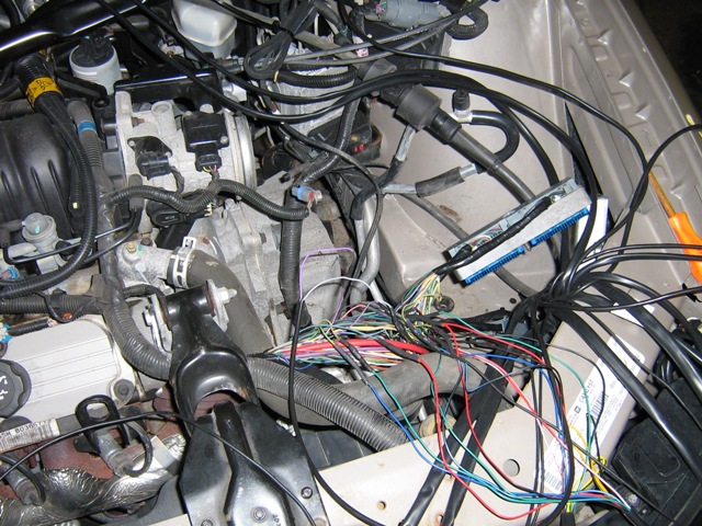
The really technically challenging part of an injection conversion is splicing the propane system's wiring into the engine's wiring harness. On universal systems, the installer has to figure out which wires to splice into. On model-specific systems, the kit manufacturer's wiring diagram specifies exactly which wires go where. On the Impala, the vehicle's computer is located in the airbox and splices were made near the PCM connectors. |

After the wires have been soldered and the shrink tubing has been shrunk onto the splices, the wires have to be neatly re-wrapped for an OEM-like appearance. |

The easiest way to run the propane system's control panel wire into the vehicle is through the grommet on the firewall. |

The fuel pump relay is spliced into the wiring harness in the fuse panel. It's neater to make the splice under the panel. |

The wiring is completed and the excess wire is bundled for storage in the fender. |
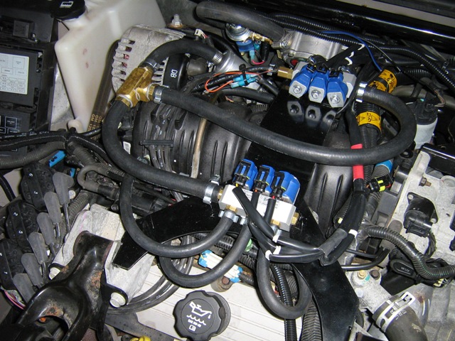
The completed underhood propane system with all wiring and hardware in place. |

A good installer thinks of the future maintenance needs of his customer. A poorly positioned fuel tank on this vehicle could cost the vehicle owner hundreds of dollars and several days of downtime if he installs the tank over the fuel pump. The panel in the floor provides access to the fuel pump. The fuel tank is located right behind the rear seat so extreme care must be taken with mounting the propane tank. |

Rather than mounting the propane tank's front bracket into the floor, Peter bolted it into the wheel house. |

The front bracket after a coat of white paint. |

The propane tank's front bracket bolt viewed from the wheel well. |

The propane tank mounted into position as viewed from the rear seat. |

The fuel pump is still accessible for service without having to first remove the fuel tank or even loosen any tank bolts. |

The propane tank's rear bracket. The spare tire is still fully accessible even though the bracket bridges over the spare tire well. |

The service valve on modern conversions is electric so the valve is only open when the vehicle is running on propane. I brought this misalignment to the attention of Sleegers and I expect they will rectify this situation. |

The best place to locate this hole is on the driver side. The exhaust pipe runs on the other side which would make the installation much more complicated. A very sharp hole saw is required to cut this hole because of the extra thickness of the floor beside the frame rail. The bolt in front of the hole secures the rear bracket of the propane tank. And yes, the screws were trimmed shorter. |

The vapour box on the propane tank leads outside of the vehicle. This ensures that any leaks or blow-offs from the safety relief valve do not cause a dangerous explosive fuel mixture inside the vehicle. |

The bumper on Impala has a very conveniently located hole in the bumper's reinforcement, which is perfect for installing the flush-mount Airod filler valve. The Airod is a bit more expensive than the Sherwood fill valves but is much more attractive. A 2-5/8" diameter hole is required to mount this filler valve in the bumper. In Canada, all hoses must be purchased as hose assemblies. The silver tag indicates the certification. |

Extensions were welded onto the fuel line brackets to extend them slightly so the propane liquid line could be supported. |

Running the propane fuel line with the other fuel lines makes for a neat installation. The cable hanging down around the engine's cross member is for the propane tank's level sensor and solenoid valve. |

To be on the safe side, we ordered 1' more liquid propane line than was required. Sometimes it's better to be looking at it than looking for it. Luckily, the vapour box had plenty of room to store the surplus hose. To overcome the service valve's misalignment, it was reoriented to curve around inside the box. |

The fuel tank as mounted in the trunk. This is a 16x36 tank which holds 82 litres (21.6 US gallons) of propane. The extra capacity of this larger tank improves the chances of only having to fill up at the cheapest stations. For a more trunk room, the 14x38 tank (68 litres / 18 gallons) should be used instead. |

Canadian regulations require that a propane sticker be applied to the right hand side of the rear of the vehicle. |

An ideal place for the propane system's control panel is on the left side of the instrument panel. However, a 12 mm hole must be drilled in the instrument panel for the cable. A flashlight shining on the back of panel shows where potential interferences are located. We used a pencil to mark those interferences on the front. It's a good thing we didn't drill first and ask questions later. |

A mirror shows the mounting clip that is located exactly where we want to drill the hole. |

Using the same flashlight trick, we can mark the locations of the mounting clips in a different location. There is plenty of room here to drill a hole beside the fog lamp switch. |

The propane system's control panel finally mounted. The panel is equipped with a very sticky adhesive so be sure it's aligned properly before you press it into position. The fuel tank level is indicated by the four green LEDs (indicating full). The orange LED indicates that the engine is running on gasoline and the green LED under the "G" (which is actually flashing) indicates that the system is waiting to switch over to propane. |

The switch-over occurs at a predetermined temperature and RPM. You can see the engine is fully warm and the orange LED is now out. When the tank level or the fuel pressure is too low, the system automatically switches back to gasoline. |

The final part of the conversion is setting up the fuel map. The SVIS has a fuel map table that relates propane injector pulse width to gasoline injector pulse width and RPM. This must be done for each universal SVIS conversion but the model-specific SVIS kits include this programming. Ideally, model-specific kits should run properly out of the box but fine-tuning is sometimes useful for a perfect operation. When setting the fuel map, the sum of the short and long term fuel trims should be as close to zero as possible at all times. This requires the use of an OBDII scanner during the fuel mapping process. We've got an ElmScan 5 USB connected to the laptop to read the OBDII codes. |